Detailed Structural Design &
Shop Fabrication Drawings
Comprehensive manufacturing package prepared for steel fabricators, welding inspectors (CWI), CNC pipe profilers, and site rigging engineers. All dimensions conform to AISC 360-16, AWS D1.1, and Eurocode 3.
1. General Structural Notes & Design Criteria
Applicable Standards
- AISC 360-16: Specification for Structural Steel Buildings.
- AWS D1.1 / D1.1M: Structural Welding Code — Steel.
- ASCE 7-16: Minimum Design Loads (Wind, Live, Thermal).
- EN 10219: Cold-formed welded structural hollow sections.
- EN 1090-2: Execution of steel structures (Exc 3).
Design Loading Criteria
- Basic Wind Speed (V): 38 m/s (137 km/h) [ASCE 7]
- Roof Live Load (Lr): 0.57 kN/m² (12 psf)
- Roof Dead Load (DL): 0.38 kN/m² (PPGI + insulation + purlins)
- Collateral / Rigging: 0.25 kN/m² (Chandeliers, audio arrays)
- Central Chandelier Hoist: 1,500 kg (Point Load at Apex)
- Temperature Range: ΔT = ±25°C
Material Metallurgy
- Pipes (CHS): EN 10219 S355J2H (Fy = 355 MPa, Fu = 490 MPa)
- Built-up Plates: ASTM A572 Gr 50 / S355JR (t = 8 to 50mm)
- Bolts: ISO 4014 Gr 10.9 & 8.8 HSFG (Preloaded)
- Anchor Bolts: ASTM F1554 Gr 55 Galv (M30, 900mm embed)
- Welding Electrodes: E70XX low-hydrogen (UT 100% CJP)
2. Master Geometric Node Table (Setting-Out & CNC)
3. Critical Connection Details & Shop Drawings
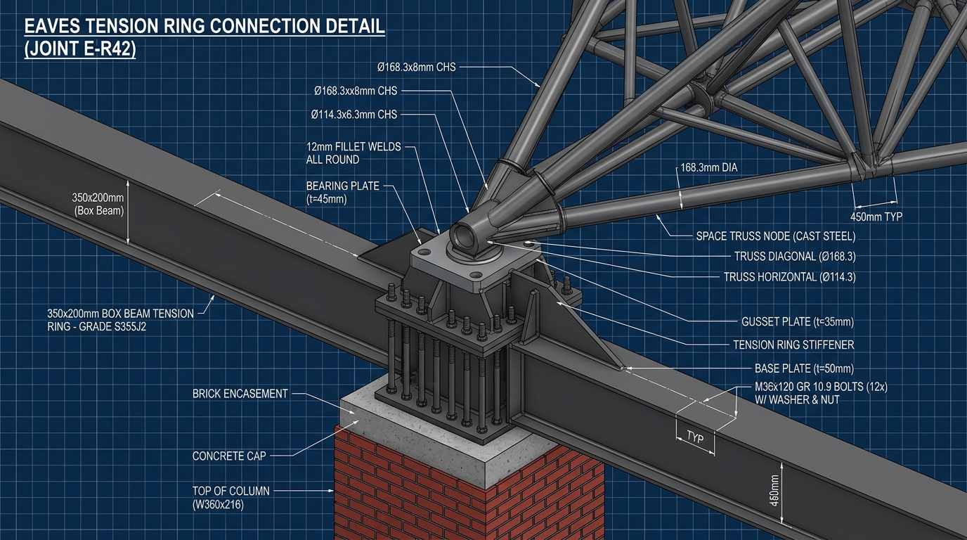
Eaves Tension Ring & Column Head Moment Connection (Joint E-R42)
Box Beam 350×200×8mm • 12× M36 Gr 10.9 HSFG Bolts • 50mm Baseplate • Cast Steel Shoe
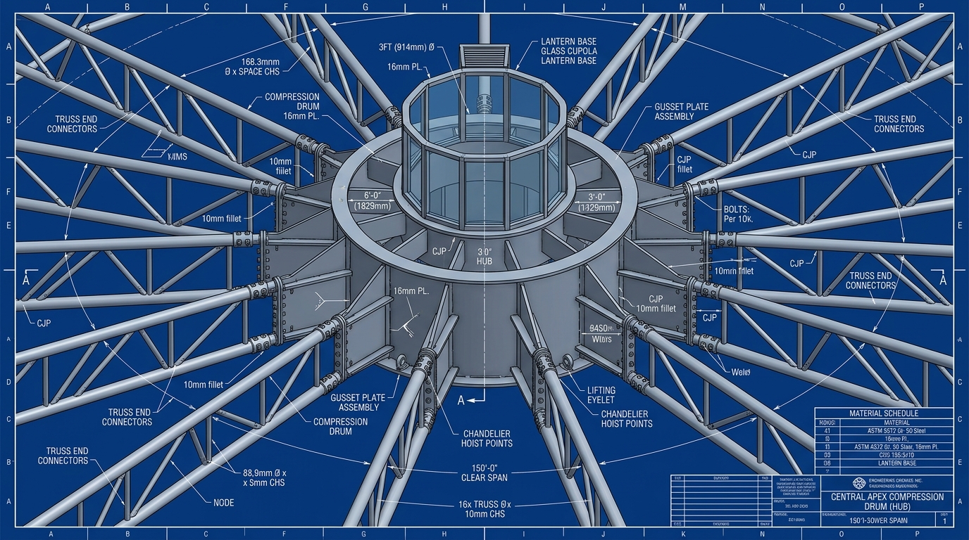
Central Apex Compression Drum & Cupola Lantern Base (Hub H-01)
Ø 6'-0" (1,829mm) Cylindrical Shell • 16mm PL • 16 Radial Shear Cleats • Chandelier Hoist Ring
4. Radial 3D Inverted-Delta Truss Shop Geometry & Splice
Fabricator Jig & Welding Protocol:
1. Top Chords (2x): Continuous Circular Hollow Section CHS Ø114.3 × 4.5 mm spaced at exactly 600 mm (24") on centers. Fitted with cold-formed purlin saddles (100×65×8mm angles) welded at 1.50 m centers along the slope.
2. Bottom Keel Chord (1x): CHS Ø114.3 × 5.4 mm (Grade S355J2H). Pre-cambered to 45 mm at midspan to counteract full dead-load deflection.
3. Web Diagonals: CHS Ø48.3 × 3.2 mm tubes profiled using 5-axis CNC pipe contour cutters to achieve complete wrap-around saddle welds per AWS D1.1 Figure 9.8 (Tubular T-, Y-, and K-Connections).
5. Column Baseplate, Pedestal & Foundation Anchorage
Anchorage Specification Matrix
- Column Section: Box 300×300×8mm (Fy = 355 MPa)
- Baseplate Size: 550 × 550 × 28 mm thick (ASTM A572 Gr 50)
- Anchor Bolts: 4 No. M30 Grade 8.8 (or ASTM F1554 Gr 55)
- Bolt Embedment: 900 mm into reinforced pedestal with bottom anchor plate (100×100×12mm)
- Grout Layer: 50 mm high-strength non-shrink cementitious grout (min 60 MPa at 28 days)
- Stiffener Gussets: 4 No. 150×150×12 mm triangular stiffeners welded to column flanges
- RC Pedestal: 600 × 600 mm with 8-T20 vertical bars and T10 ties @ 150mm c/c
Concrete Foundation Package
Each of the 16 columns is supported by an isolated reinforced concrete pad footing:
6. Site Erection Rigging & Tandem Crane Lifting Plan
Erect all 16 perimeter columns. Assemble the 16 segments of the Box 350×200 tension ring beam at +20'-0". Fully torque all 12×M36 splices before roof loading. Verify perimeter circular tolerance ($\pm 5 ext{ mm}$).
Erect a heavy-duty 4-leg modular shoring scaffolding tower at the exact geographic center (height +37'-6"). Mount the Ø 6'-0" apex compression drum on 4 calibrated 50-ton hydraulic leveling jacks.
Lift 3D space trusses in diametrically opposite pairs using a 50-ton mobile crane: Truss 1 & 9 first, followed by Truss 5 & 13, then diagonals. Bolt securely into the apex drum and eaves tension seats.